Home
Uncategories
Schematic 555 Timer Circuit Diagram / How Can We Make A Timer Of 5 Minutes Using 555 Ic Timer Quora - One reduces the trigger sensitivity and the other will double the output pulse duration without increasing the r1 and c1 values.
Schematic 555 Timer Circuit Diagram / How Can We Make A Timer Of 5 Minutes Using 555 Ic Timer Quora - One reduces the trigger sensitivity and the other will double the output pulse duration without increasing the r1 and c1 values.
Schematic 555 Timer Circuit Diagram / How Can We Make A Timer Of 5 Minutes Using 555 Ic Timer Quora - One reduces the trigger sensitivity and the other will double the output pulse duration without increasing the r1 and c1 values.. The next diagram shows the basic current consumption of 555 timer chips from different manufacturers. See more ideas about timer, electronics circuit, circuit. To set the time duration of this circuit we have used a 550kω variable resistor. The following schematic shows two additions to the basic 555 timer circuit. An ic timer ic 555 is a number of major equipment.
This circuit can be used as rain sensor, water overflow sensor or as a water level sensor. This pin should be connected to ground. Check out the huge collection of 555 timer based circuits here. You can for example use it to reverse the direction of a robot when it bumps into a wall. One reduces the trigger sensitivity and the other will double the output pulse duration without increasing the r1 and c1 values.
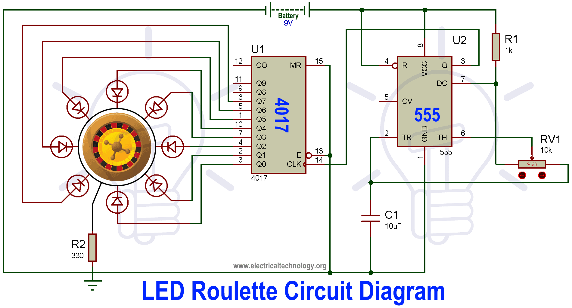
Led Roulette Circuit Diagram Using 555 Timer Ic 4017 Counter from www.electricaltechnology.org After one minute of time duration, the led will automatically turn on. The following schematic shows two additions to the basic 555 timer circuit. Here, we take a look at some 555 timer circuits based on the ic. Resistive network consists of three equal resistors and acts as a voltage divider. Derivatives provide two or four timing circuits in one package.it was commercialized in 1972 by signetics. We can use this property of 555 timer to create various timer circuits like 1 minute timer circuit, 5 minute timer circuit, 10 minute timer circuit, 15 minute timer circuit, etc. The 4rth circuit diagram shows the standard ic 555 adjustable timer circuit having two sets of timing ranges and an output relay for toggling the desired load. 555 ic timer block diagram 555 ic timer block diagram.
Let us discuss in detail about this circuit.
Pin 2 detects a voltage below 1/3 of the supply voltage to turn the ic on. In 2017, it was said over a billion 555 timers are produced. Suitable for various test circuits. 555 timer bistable example circuit. The following example shows the 555 timer in bistable mode. Check out the huge collection of 555 timer based circuits here. Look at the block diagram again. This integrated circuit can be used in a variety of ways from which the basic one is to produce accurate and stable delays in electronic circuits.additionally, it is available in 8 pin dip and 14 pin dip. 555 timer, as the name specified, are the electronics circuits used for measuring time intervals.in this article, we will cover about 555 timers. Resistive network consists of three equal resistors and acts as a voltage divider. Once you finish the basics, learn some really basic 555 timer circuits like a monostable circuit, an astable multivibrator and a 555 timer based oscillator circuit. Working knowledge of duty cycle; Hi, i'm trying to build a 555 timer circuit that has an output low time of 5 minutes and an output high time of 250 milliseconds.
555 timer, as the name specified, are the electronics circuits used for measuring time intervals.in this article, we will cover about 555 timers. Rain alarm using 555 timer. An ic timer ic 555 is a number of major equipment. We need to set 555 timer in monostable mode to build timer. 555 datasheet 555 duty cycle 555 metronome 555 reset function 555 time delay relay inverted 555 timer pulse generator.
555 Adjustable Timer Part 1 4 Steps Instructables from content.instructables.com 555 timer, as the name specified, are the electronics circuits used for measuring time intervals.in this article, we will cover about 555 timers. We can use this property of 555 timer to create various timer circuits like 1 minute timer circuit, 5 minute timer circuit, 10 minute timer circuit, 15 minute timer circuit, etc. In monostable mode, the duration for. Two tone generator circuit using 555. Once you finish the basics, learn some really basic 555 timer circuits like a monostable circuit, an astable multivibrator and a 555 timer based oscillator circuit. From our earlier discussions we know that for a 555 in the delay timer mode, the delay could be accurately managed through a single external resistor and one capacitor. These on off intervals can be adjusted by varying the 555 timer output and number of counter outputs. Pin 2 detects a voltage below 1/3 of the supply voltage to turn the ic on.
Look at the block diagram again.
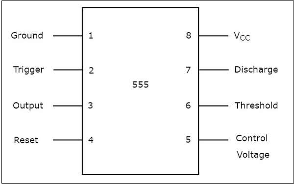
Simple 555 timer circuits & projects. Hi, i'm trying to build a 555 timer circuit that has an output low time of 5 minutes and an output high time of 250 milliseconds. Before going into detail of time delay circuit, first we need to learn about 555 timer ic first.below you can find the pin diagram of 555 timer ic along with the details of each pin. The 4rth circuit diagram shows the standard ic 555 adjustable timer circuit having two sets of timing ranges and an output relay for toggling the desired load. When this circuit is powered it will initially stay off. 555 timer, as the name specified, are the electronics circuits used for measuring time intervals.in this article, we will cover about 555 timers. The reset input current draw illustrates the need for a current limiting resistor as shown in some of the preceding circuits. Over 100 of 555 timer circuits and projects including the ic datasheet. 555 timer bistable example circuit. Here, we take a look at some 555 timer circuits based on the ic. The 555 timer ic is an integrated circuit (chip) used in a variety of timer, delay, pulse generation, and oscillator applications. This integrated circuit can be used in a variety of ways from which the basic one is to produce accurate and stable delays in electronic circuits.additionally, it is available in 8 pin dip and 14 pin dip. 555 timer ic is wired as a astable multivibrator.
A collection of 555 circuits using the 555 timer as an astable oscillator with different duty cycles. Once you finish the basics, learn some really basic 555 timer circuits like a monostable circuit, an astable multivibrator and a 555 timer based oscillator circuit. Although the schematic looks correct, this basic circuit may actually have a few negative aspects. 555 timer, as the name specified, are the electronics circuits used for measuring time intervals.in this article, we will cover about 555 timers. This pin should be connected to ground.
555 Timer Tutorialspoint from www.tutorialspoint.com I hope you more understand. Rain alarm using 555 timer. Check out the huge collection of 555 timer based circuits here. The next diagram shows the basic current consumption of 555 timer chips from different manufacturers. Because of their availability and ease of use, the 555 astable circuit is the common source of clock signal in many synchronous circuits. All we need to change the value of resistor r1 and/or capacitor c1. An ic timer ic 555 is a number of major equipment. In monostable mode, the duration for.
The reset input current draw illustrates the need for a current limiting resistor as shown in some of the preceding circuits.
555 timer was first introduced by signetics corporation in 1971 as se555/ne555. The 4rth circuit diagram shows the standard ic 555 adjustable timer circuit having two sets of timing ranges and an output relay for toggling the desired load. 555 timer is an industrial standard ic existing from early days of ic. On pressing the switch s1, the ic will get the voltage and start its operation. Suitable for various test circuits. 555 timer bistable example circuit. Two tone generator circuit using 555. Rain alarm using 555 timer. For 5 min, 10 min and 15 min you just have to change the resistor value (r 1). Working time is determined by the 220k potentiometer and capacitor c1. Derivatives provide two or four timing circuits in one package.it was commercialized in 1972 by signetics. The 555 timer is a simple integrated circuit that can be used to make many different electronic circuits. Here is a simple and interesting hobby circuit that can be made using the popular 555 timer ic.

0 Comments:
Posting Komentar